
Pro Controller Configuration
Basics:
Getting Started:
Step 1 - Physical Connections
Step 2 - Powering Up / Down
Step 3 - Connecting to WiFi
Step 4 - LED Groups
Step 5 - LED Effects
Step 6 - Scenes
Other
Basics - Pro Controller
The Computer Controller is the intelligence behind the system. It connects to the first LED in the chain, and issues commands to control all the LEDs, individually if required. It can also play sounds to enhance the lighting effects, and provides a web interface for configuration and control.
The controller has 2 individual data out pins for controlling two chains of LEDs. Both can be configured as either RGB or RGBW. In addition to the sound output, there is also
a HDMI video output for connecting to HDMI screens of any size.
Basics - LEDs
Each LED unit contains a Red, Blue, and Green micro LED, which allows over 16.5 million color combinations. At maximum brightness each LED can theoretically draw 60mA (20mA max for a single color eg red or dedicated white).
The LED chips require 5V DC, and are connected in a daisy chain - with a Data In and Data Out connection.
The LED units are available in single units (requires soldering), single interlocking (no soldering required) or strip versions, depending on your requirements.
You can also connect a lens cover to the LED units in order to run fibre optic cable for small spaces.
The LEDs are 'numbered' according to their position in the connected chain - the 1st LED is LED 1, 2nd is LED 2 etc.
Step 1 - Physical Connections
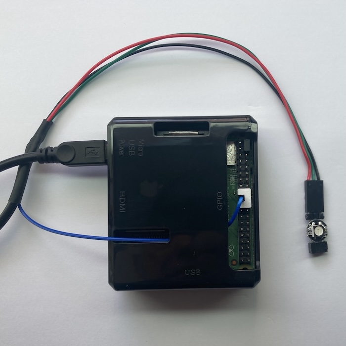
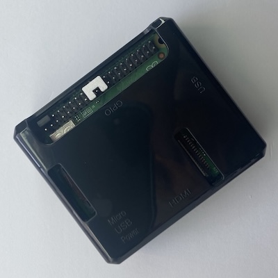
First, connect the single wire LED data cable from the USB lead to the Computer Controller data output pin. Connect to pin 19 as shown, which is the 10th pin down from the top left, and is surrounded by a white header. DO NOT CONNECT TO ANY OTHER PIN!!
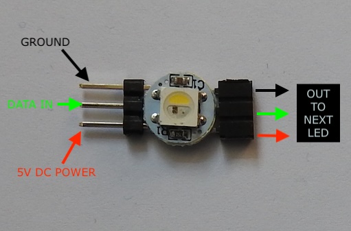
Next, connect the power/data cable to the first LED as shown. IMPORTANT: the red cable goes to the 5V connection, bottom left of the LED chip as shown.
You can connect more LEDs or strips using the interlocking connectors - but take note of the orientation to ensure that 5V goes to 5V, and ground goes to ground etc.
Step 2 - Powering up / down
The controller requires 5V DC. Connect a micro USB lead to the controller to provide power. This can be from a mains adapter rated at 5V, or USB battery power pack if required.
As soon as you connect the USB lead to the controller, and the other end to a power source, the controller will turn on.
It is strongly recommended that you do NOT disconnect power without first shutting down the controller safely. There are several ways of doing this, either from the configuration web interface or control app (see below), or by
shorting pins 39 and 40 (the bottom two pins) momentarily. Once done, you will see a green LED inside the controller flash for several seconds before turning off. It is then safe to remove power.
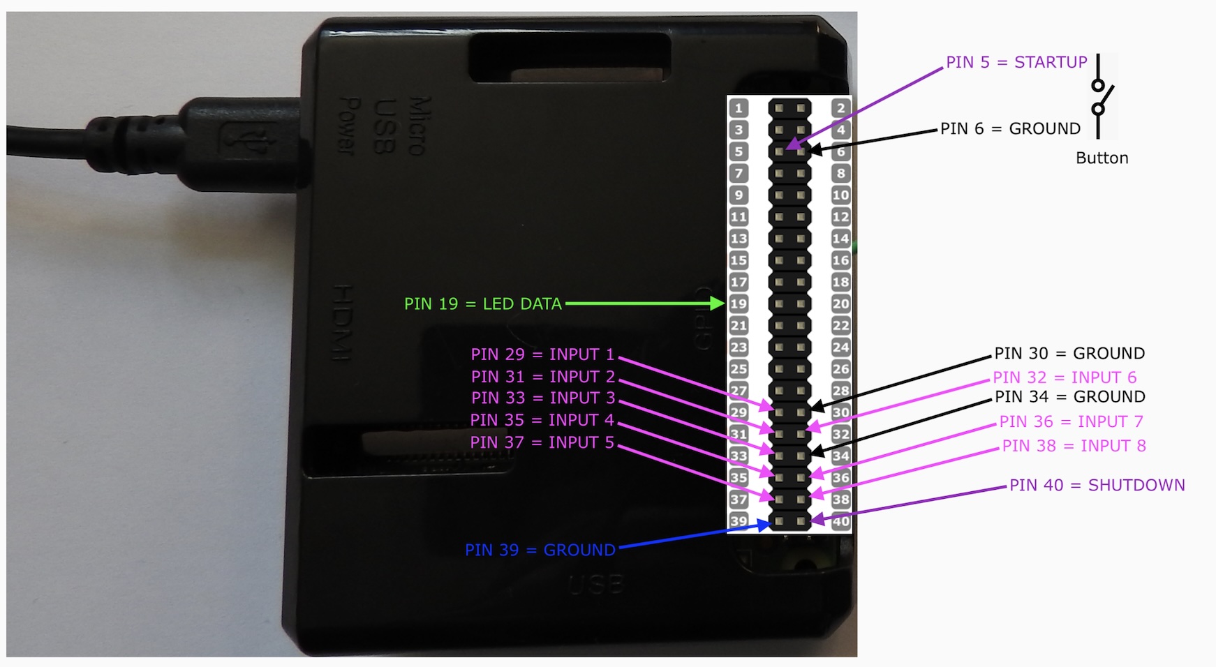
Having shut the controller down this way, and with power still connected, you can restart the controller by shorting out pin 5 with ground as shown above.
Often model builders connect push to make buttons to the controller pins 39/40 and 5/6 to allow safe shutting down / powering up
If you disconnect power and re-connect, the controller will turn on again automatically.
Step 3 - Connecting to WiFi
When the controller powers up, it will begin broadcasting a WiFi network called 'Inner Light'. Connect to this network with your computer using the default password: 'innerlight' (lowercase, all one word).
Once connected to the 'Inner Light' network, you can then connect to the main web interface by browsing to the following address:
http://192.168.1.100
or
http://il.local
You can also use https in place of http for a more secure connection - note depending on your browser you may receive a https certificate warning.
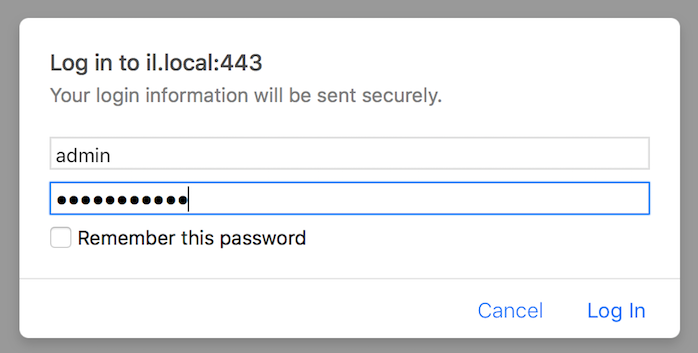
You will then need to log in using the username: 'admin' and the web interface default password 'password' (this can be changed in the settings).
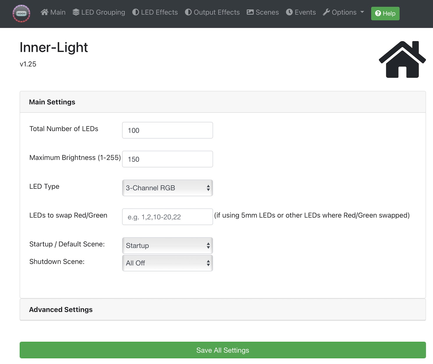
Once you have logged in, you should see a screen similar to the below with menu options across the top for the various functions:
Step 4 - LED Groups
These are the groups of LEDs that you want to individually control. LEDs are numbered according to their position in the connected chain. An LED Group can consist of one or more LEDs. You can create as many LED Groups as you wish, and the same LEDs can be listed in multiple groups if needed.
LED Groups are organised into folders. Clik on the 'Main Folder' to see / create LED groups within that folder, and you can create your own folders if needed to organised your LED groups.
Enter the LED numbers, starting at 1, separated by commas. To include a range, use the - symbol, eg 5-10 would include LEDs 5,6,7,8,9 and 10.
You can choose to enter either the LEDs to include, or the LEDs to exclude - for example to affect all LEDs except for specific LEDs, choose this option.
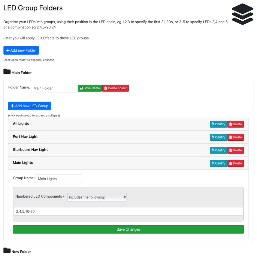
Clicking 'Identify' will make the LEDs flash red so that you can easily identify them in your model before proceeding.
Step 5 - LED Effects
An LED effect is a description of what you want your lights to do. An example would be flashing red, or fading from one color to another, or simply to statically emit a particular color.
You can create as many effects as you wish to achieve your desired result. LED effects themselves are independent of specific LEDs at this stage - you will assign effects to your LED groups in the Scenes section.
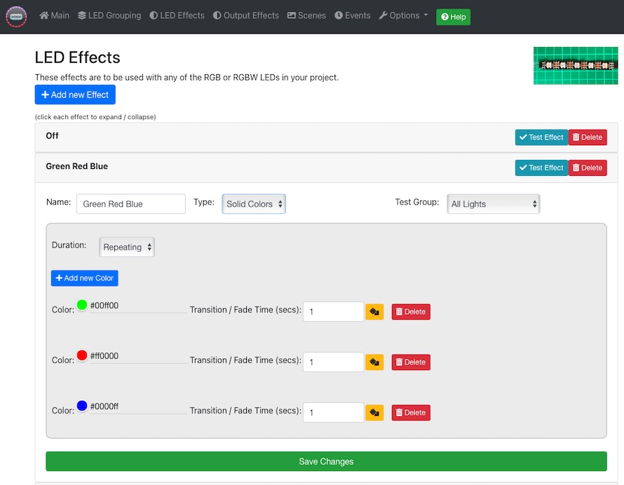
Each LED effect should be given a unique and meaningful name, eg 'Flash Green'
You should then choose from the available effect types and enter the parameters (NOTE: the dice symbol button can be used to enter random values, from a minimum to a maximum):
Solid
A solid effect instructs the LED(s) to fade from whatever they are currently, to the target , using the transition / fade time specified. A fade time of 0 means the LED will immediately change to the selected .
You can add multiple to the effect, with different timings, and choose whether the effect happens once, or happens continuously:
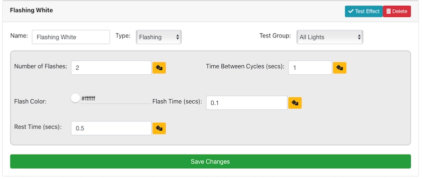
Flashing
As the name suggests, this effect type causes the LED(s) to flash a particular , with the timings you specify:
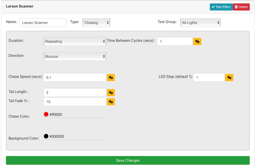
Chasing
A Chasing effect involves more than one LED, where the moves along the chain of LEDs. There are various options to try, eg forwards, backwards, bounce, converge on LED etc:
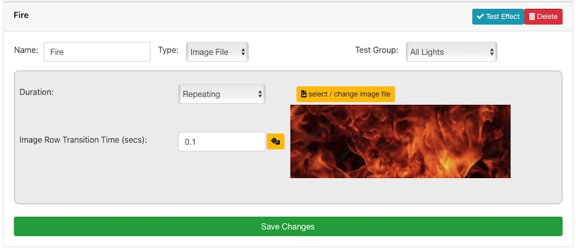
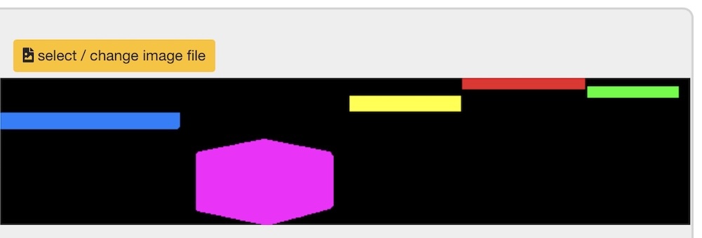
Image
The image effect is perhaps the most flexible effect. It requires a bitmap image file, which you can create or download, and the controller will scan the image top to bottom, row by row, and apply the from the image onto the target LEDs (averaging the if necessary), at the speed you select. Example shown below:
Step 6 - Scenes
Scenes are a way of linking LED Groups with LED Effects, and also optionally including sound / video effects and switching output devices. You can create as many scenes as you wish. Each scene can include zero or more lighting / output effects, and zero or more sound / video effects.
Each lighting or sound element can be delayed by an amount of time, if desired. The time can be random by using the 'dice' button, or entering minimum and maximum parameters separated by a - symbol, eg 1.0-5.0
It is perfectly valid for many lighting effects and sound files to be simultaneously playing at the same time - though any given LED can only be part of a single lighting effect at any one time, which would be the last effect applied to that particular LED.
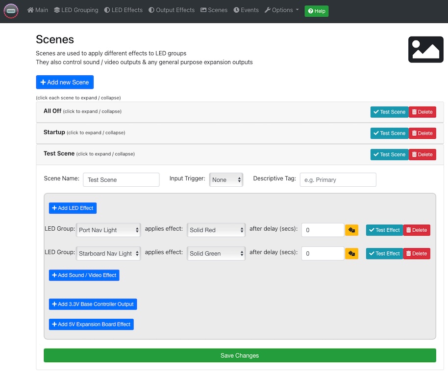
You can create as many scenes as you wish, and initiate them via the web interface (using the 'Test Scene' button) or via a control app.
Advanced - Audio / Video
When adding a sound or video file to one of your Scenes, you can specify the volume, an optional delay, and whether to play the file once or continuously on a loop. Note sound files (eg .mp3, .wav) will be played out of the audio jack output of the controller. Video files (eg .mp4) are played out of the HDMI output of the controller. It is possible to play multiple sound files at the same time.
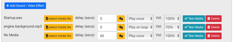
Note: to stop sounds or videos from playing, add a sound/video effect, but do not choose a file. This action will cause all playing sounds/videos to cease playing.
The below shows example wiring diagram for the audio output using the amplifier / speaker sold in the store, where power for the amplifier is extracted from the LED connection:
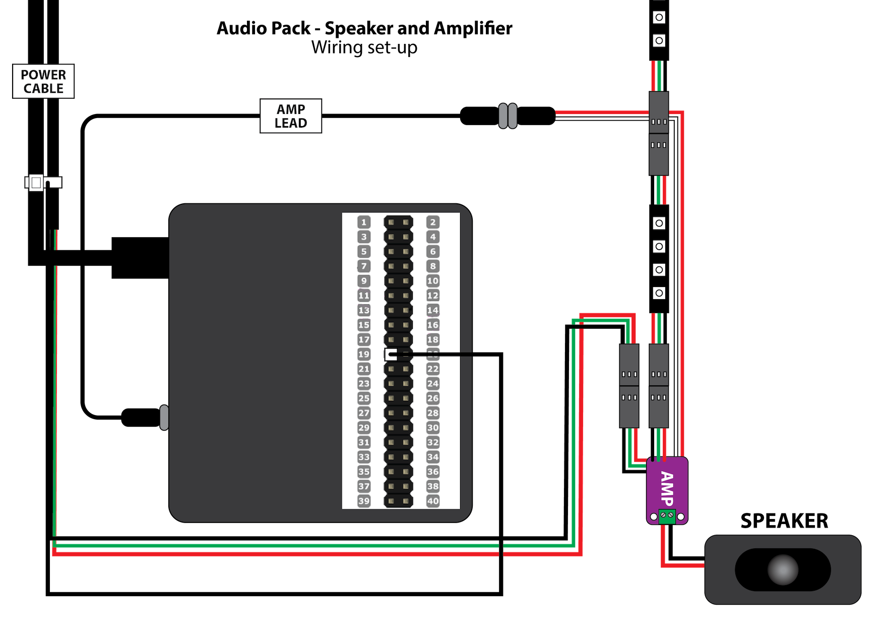
You can test the audio output simply by connecting a pair of headphones to the audio output of the controller. If using HDMI, the screen must be connected prior to powering up the controller.
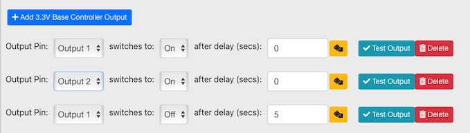
Advanced - 3.3V Output Pins
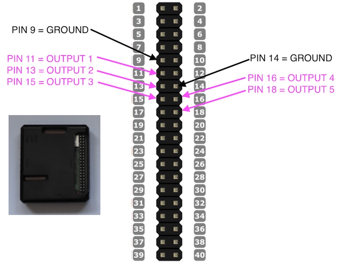
There are 5 output pins available on the Pro controller which can be set to 0V (Off) or +3.3V DC (On) with a command. Each output pin can deliver max 16mA, with 50mA total across all outputs.
These output pins can be used (via a 3.3V relay if necessary) to control equipment which requires an On or Off state, eg a relay, motor, standard LED, laser module, or other device.
You can affect the state of the output pins when you activate a scene:
The physical connections to these output pins is as follows. Care must be taken to connect to the correct pins!
Advanced - Expansion Board
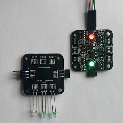
The expansion board lets you control up to 6 standard 5V DC devices, eg regular LEDs. It sits within the normal LED connection chain, and uses the same protocol as the smart LEDs used with the controller. Two on-board RGB LEDs are also included, which can be used with the fibre optic connectors if required. Multiple boards can be daisy chained together, or inserted anywhere on the addressable LED data line.
The board takes up either 4 x RGB LED slots, or 3 x RGBW slots - it is compatible with either type of LED system. 500mA max per output.
The boards are connected in the same way as the addressable LEDs - taking power & data in, and connecting data out to the next expansion board or LEDs. You then take +5V and ground (LEDx) from each output to control standard LEDs or other 5V devices.
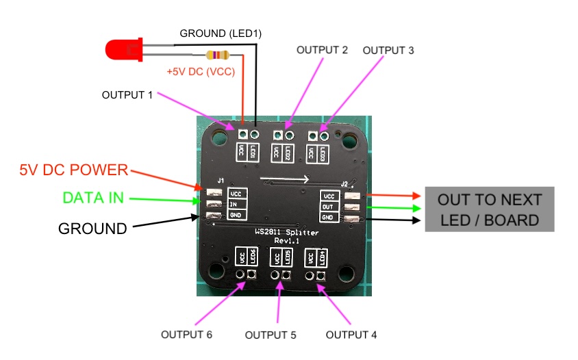
You control the board outputs as part of a scene - specifying the board 'address', output number (1-6) and required level (0-100%). The board address is similar to the other LED addresses, ie their position on the data line, eg if the board was connected to the data out of LED 10, then the board address would be 11, then the next LED/Board address would either be 15 (if in RGB mode) or 14 (if in RGBW mode).
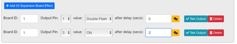
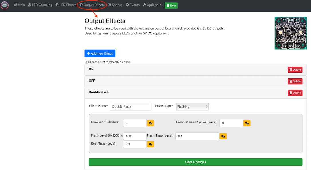
The effects applied to each output are defined in the Output Effects section:
Advanced - Events
The 'Events' menu option allows you to specify one or more conditions under which to activate a scene etc. There are 3 self explanatory options: 'after a set period of time' from when the controller is powered on, 'repeatedly, every x mins/secs' and 'when a usb key is pressed' (see next section)
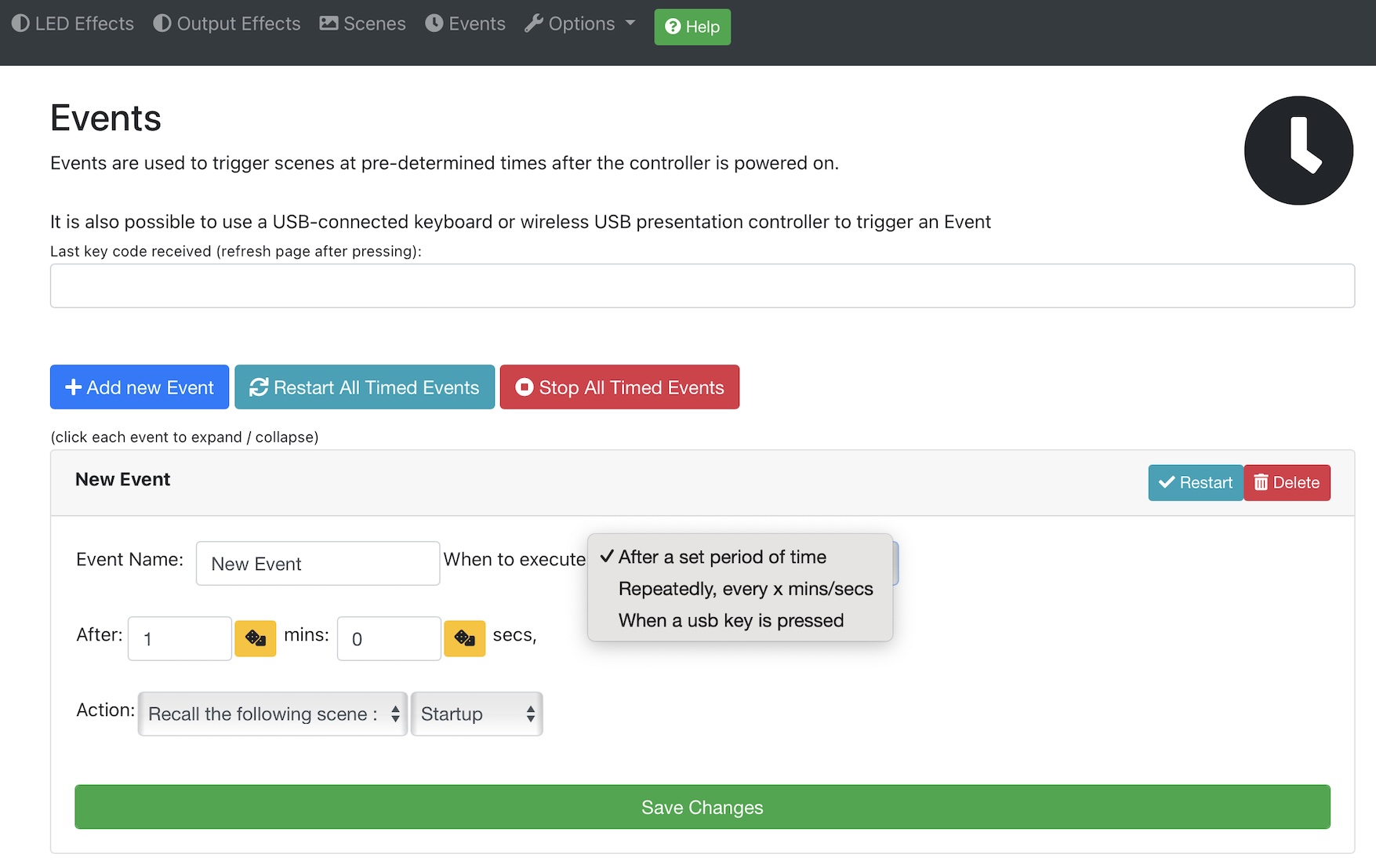
Note if you choose to recall a random scene, can you optionall specify a tag description (which can you enter against the scene in the scenes section) to narrow down the choice of available scenes.
Advanced - Control Options
There are several ways of activating your scenes. Firstly, the controller will automatically activate the scene specified as the 'Startup Scene' from the main menu. Equally, the 'shutdown scene' specified is activated when the controller is shut down. Typically this would be an 'Off' scene where LEDs are made black (off)
Physical Buttons
You can also activate scenes and startup / shutdown the controller using physical 'push to make' buttons connected to the controller, which supports up to 8 for scenes, plus a startup and shutdown option.Note pin 40 (Shutdown) also serves as a factory reset option. if the unit is powered up whilst the button is pressed (ie whilst pin 40 is connected to one of the ground connections), the unit will default to factory settings.
Connect any of the input pins to ground to activate the function:
Network Commands
You can send network commands from any 3rd party system to initiate scenes. The commands are HTTP/HTTPS GET requests. Here is an example command which activates a scene called 'Startup':https://admin:password@192.168.1.100/api/scenes/Startup/apply
Replace 'password' with your web password (if you have changed it). Replace 'Startup' with the name of your scene. If your scene contains a space, use %20 in the command instead of the space character, eg 'Main%20Startup' instead of 'Main Startup'
Replace '192.168.1.100' with the IP address of your unit, if it is connected to your network (you can also use IL.local in place of the IP address, depending on your computer / network). If sending the command from an external source, eg IFTTT.com, use the external IP address of your network, and ensure that port 443 TCP is forwarded through your router (and that you are not using the default password)
You can test these commands by simply entering the URL into a browser which is able to reach the IP address specified.
USB Keyboard Entry
You can also specify, in the 'Events' section (see previous section) one or more keyboard codes entered via a connected USB keyboard or device, to activate scenes etc. This would include the USB wireless controller accessory from the store: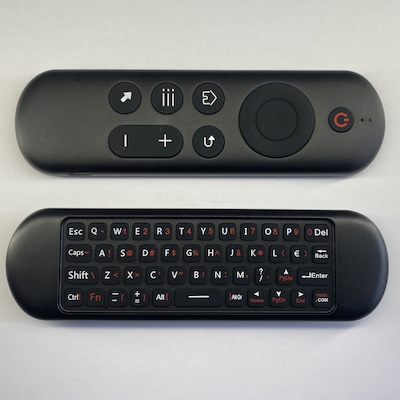
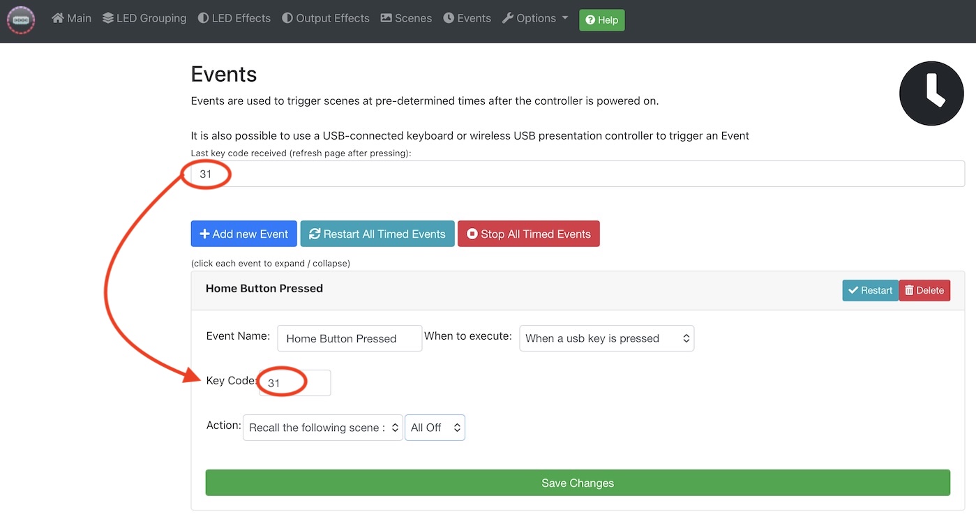
To implement these, connect the USB keyboard / device to the controller, and then power the controller on. Navigate to the Events section, and then press one of the buttons on the controller / keyboard. Then refresh your browser page, and the numeric code associated with that button will appear on screen. Use that number in the Key Code section when adding your event:
Advanced - Saving / Restoring
The 'Options' menu option allows you, amongst other things, to backup or restore the complete configuration stored in the controller. This allows you to quickly swap between different models / setups. First choose the backup/restore option from the menu:
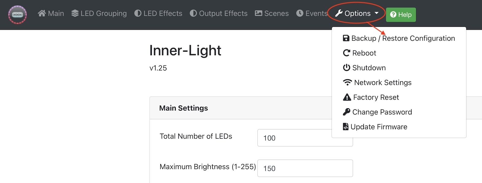
There are then two ways of saving / restoring - either using a file to/from your computer (recommended) or via a USB Flash Drive inserted into the USB connection of the controller:
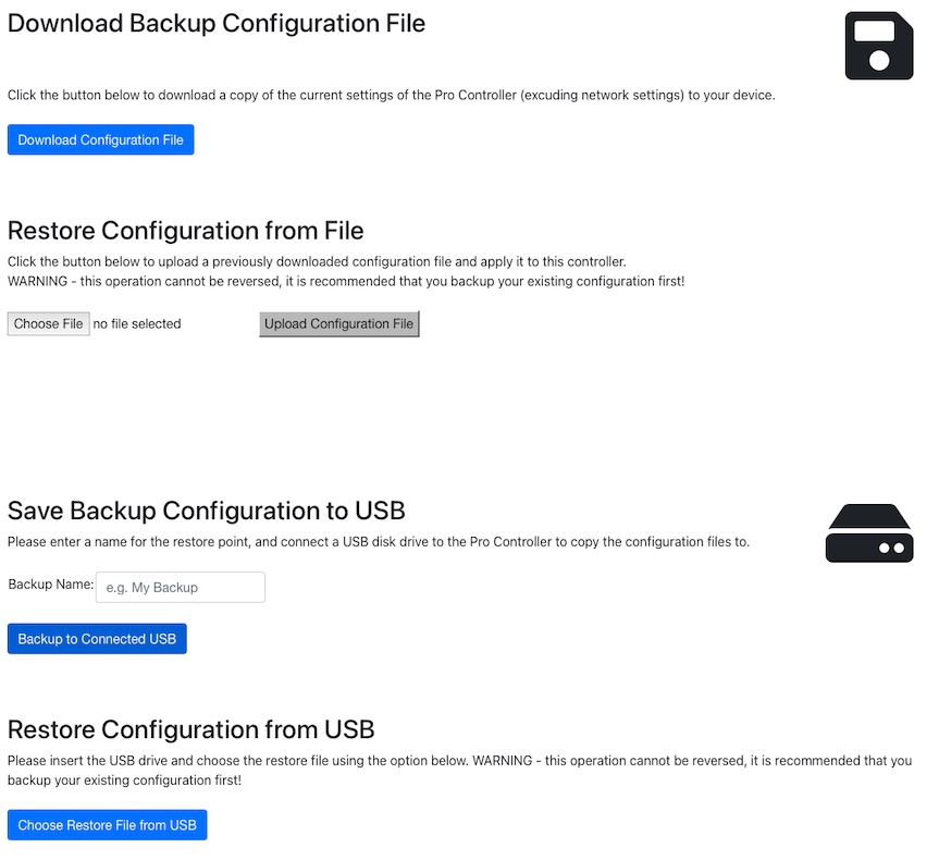
It is STRONGLY recommended that you take a backup of your settings periodically & keep them in a safe place.
Factory Reset
There are several ways to perform a factory reset of the pro controller. Note this will delete all your settings, and reset the unit to the state it was when purchased.
1. The recommended way is via the web interface, by selecting the 'Factory Reset' option from the Options menu
or:
2. If you are unable to get to the web menu (eg you have forgotten your password), connect pin 40 to Ground pin 39 (the bottom 2 pins) in order to shut the unit down, then wait 30 seconds and disconnect power momentarily, and then reconnect power with the pins still connected together to perform a reset of the WiFi and web password. The process should take around 30 seconds, after which the unit should broadcast the 'Inner Light' standalone WiFi network and be back to original settings. You can then disconnect pins 39/40.
Rewriting the SD card
If the above fails or cannot be attempted, you can rewrite the SD card which runs the Pro Controller operating system. To do this, you will need some software which writes disk images to SD cards, such as Win32DiskImager. A copy of Win32DiskImager for Windows can be downloaded by clicking HEREIn addition to the image writing software, you will also need the disk image itself, please email in to request the latest link.
Once you have the image file (large file ~4GB), you can remove the SD card from the Pro Controller, insert it into your computer (using a micro-SD adapter if required) and use the disk writing software to write the disk image to the SD card. When complete, eject & remove the SD card from your computer & re-insert into the Pro Controller & power it back up. When you connect to the web interface for the first time, there will be an 'invalid licence' error message with a long number - email that number into us and a replacement licence will be issued (please make a note of this in case it is needed in the future). You can then connect to your controller WiFi and enter the licence at http://192.168.1.100/#!/licence
Troubleshooting
The following may help when attempting to troubleshoot problems with the system, for example if lights are flashing randomly, or colors are not as expected.
Power Issues
One quick test is to reduce the maximum brightness setting significantly to see if that solves the issue - if it does, then it points to a power problem:Please refer to the power calculator section HERE
Green instead of Red!
If using 5mm rounded LEDs, or LEDs from a source other than our store, you may notice that LEDs are green when they should be red. This is normal, and caused by a slight difference in the protocol standards. To rectify, simply add the numbers of any LED which behaves in this way (typically all the 5mm LEDs) to the main section under 'LED to swap Red/Green'Equally, if the reverse occurs, check that you have not previously entered the LED numbers in that section and subsequently altered the LED arrangement.
Wireless Interference
It has been observed that some installations of the system, particulary those with long runs of cable, experience interference on the data line caused by nearby wireless signals - where the cable effectively acts as a wireless antenna. This can result in random flashing of certain lights etc. It is good practice to use one of the circular LED chips at the very start of the data line, near to the base controller, and also use one at the very end of the data chain. The circular LED chips both a resistors and capacitor built in which help with the interference, whereas the 5mm or Nano LEDs for example, do not.Wiring Issues
It is important that each LED receives power, ground, and data in (and that data out goes to the next LED). A break in any cable will have consequences - particularly the ground connection, which can sometimes still allow the LEDs to function, with unexpected results.Please refer to the led connection guide HERE